Computational approaches to a robust segmental lining design in mechanized tunneling
M.Sc. Gerrit Neu
Segmental tunnel linings form the final load-bearing and sealing structure of a TBM-driven tunnel. The state-of-the-art in many countries is to design these structures using reinforced concrete (RC) segments. Recent trends in the tunneling industry are changing this paradigm, as steel fiber reinforced concrete (SFRC) is becoming more widely used worldwide. Steel fibers increase the robustness of lining segments and provide important reinforcement at segment extremities, i.e. in areas in which traditional reinforcement bars cannot be placed due to minimum concrete cover requirements. Steel fibers therefore greatly reduce concrete spalling at particularly vulnerable areas, such as at segment corners or in the vicinity of the jack loadings, which results in an increased robustness of the lining system.
The design of SFRC structures is not as straightforward as the design of traditional RC structures. Steel fibers provide a residual strength after onset of cracking depending on the type, content and orientation of the fibers. Available guidelines characterize the residual strength of SFRC based on bending tests and derive uniaxial stress-strain relationships for ULS and SLS design. In order to directly assess the influence of the individual fiber type and content on the structural behavior of segmented linings, a multi-level SFRC modeling framework was developed. The interaction between individual fibers and the concrete is captured by semi-analytical fiber pullout models, accounting for the type of the fibers (with and without hooked ends), the fiber inclination, the concrete strength as well as the bond characteristics. At the level of an opening crack, the fiber bridging effect is approximated by a traction-separation law via the integration of the single fiber pullout response of all effective fibers intercepting a representative crack, taking the orientation of fibers due to casting into consideration. For capturing the development (opening, spacing) of cracks in finite element (FE) models on the structural level, interface-elements are used and equipped with the traction-separation law determined on the crack scale. If also conventional reinforcement bars should be included in the analysis, the rebar itself can be modelled as a simple linear truss and coupled with the concrete matrix using a constraint condition between control points located on the rebar elements and their respective projection points within the elements in which they are embedded. The constraint condition also includes the bond-slip mechanism.
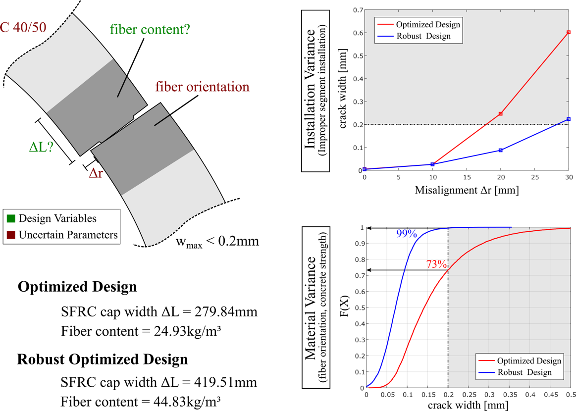
Due to the explicit consideration of major fiber and/or rebar design parameters, this multi-level model allows for a model based design of structural members containing arbitrary reinforcement schemes. In order to design a robust as well as cost-effective tunnel lining segment, optimization algorithms in conjunction with uncertainty modeling and the principles of robust design are employed. Figure 2 shows the conventional as well as a robust optimization of a hybrid lining design for the longitudinal joint. The objective of the optimization task is to minimize the fiber content and the width of the SFRC cap ΔL while a maximum tolerable crack width wmax of 0.2mm is employed as constraint condition. For the robust optimization also the variance of the maximum crack width due to uncertain material properties (concrete properties modeled as Gaussian distribution, fiber orientation modeled as interval) is included as an objective function. The optimization task is solved by the particle swarm optimization and both derived designs are shown in Figure 2 (left). In order to evaluate the vulnerability of these designs, their performance in case of an improper segment installation, resulting in a misalignment Δr between adjoining segments (Figure 2, top right), and their reliability regarding variances in the concrete strength as well as in the fiber orientation (Figure 2, bottom right) are investigated.
Contact
M.Sc. Gerrit Neu
gerrit.neu@rub.de
+49 234 / 32-29069